Programming Cable Pinouts
Kenwood K1
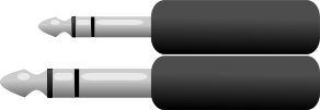
The most common connector for portable radios, originally designed by Kenwood but later became a de facto standard. It uses a pair of TRS connectors, one 2.5mm and one 3.5mm, where the smaller one is usually at the top and the big one at the bottom. A common 8 in 1 programming cable usually has it marked as K1.
- Not Connected
- TX
- Ground/GND
- Not Connected
- Not Connected
- RX
Baofeng DMR
Same form factor as the Kenwood K1, but instead of carrying serial data it carries USB. This pinout is used with all OpenGD77 compatible radios that use the K1 plug (GD-77, DM-1701, DM-1801, MD-UV380, etc).
- Not Connected
- Data +
- Ground/GND
- Data -
- Not Connected
- Not Connected
QYT 3.5mm

This cable and pinout is used on all mobile QYT transceivers like the KT-8900, KT-8900D and others. It uses a standard 3.5mm TRS Jack and requires no passive components.
- TX
- RX
- Ground/GND
Yaesu RJ11

Some Yaesu models use the front RJ11 mic connector for programming. Pin 1 is connected directly to RX, but TX goes thru a diode (anode to TX, cathode to Pin 1) Most of the time, a 10k resistor between RX and VCC is added to pull the data line high. Pinout comes from page 10 of the official manual of the FT-2900R.
- Data (RX directly + TX via Diode)
- Not Connected
- Ground/GND
- Not Connected
- Not Connected
- Not Connected
Yaesu Mini Din 6 Pin
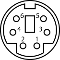
Other Yaesu models use the Data port on the back for programming, which is a 6 Pin Mini Din. Pin 4 is connected directly to RX, but TX goes thru a diode (anode to TX, cathode to Pin 4). Most of the time, a 10k resistor between RX and VCC is added to pull the data line high. For more information, I recommend checking this DIY video by LB5JJ.
- Not Connected
- Not Connected
- Not Connected
- Data (RX directly + TX via Diode)
- Ground/GND
- Not Connected
Anytone USB Mini B

This pinout is used by HF/CB export radios from Anytone like the AT-5555n II and AT-6666/Pro and the Radioddity versions (QT60 and QT80). Please note that even if it uses a USB Mini B connector, it does not carry USB Data. Pinout taken from this schematic. The female receptacle is upside down, so the pin numbers are flipped.
- Not Connected
- RX
- TX
- Ground/GND
- Ground/GND
Hyera H1
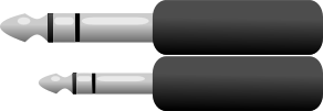
Simillar to the Kenwood K1, it also uses a pair of 2.5mm and 3.5mm connectors, but with smaller spacing between the two plugs, a different pinout, and they are flipped around (3.5mm on top and 2.5mm on the bottom, at least on my PD416). A common 8 in 1 programming cable usually has it marked as H1.
- Not Connected
- TX
- Not Connected
- Not Connected
- RX
- Ground/GND
Motorola 2.5mm
This cable is used on old Motorola models, mostly non DMR HT Radios like the Motorola EP and PRO series of handies. Pin 2 is connected directly to RX, but TX goes thru a diode (anode to TX, cathode to Pin 2) A common 8 in 1 programming cable usually has it marked as M1.
- Not Connected
- Data (RX directly + TX via Diode)
- Ground/GND
Motorola RJ45

Motorola uses a standard RJ-45 connector for programming their radios, but uses with a single pin for TX and RX. Pin 2 is connected directly to RX, but TX goes thru a diode (anode to TX, cathode to Pin 2). A common 8 in 1 programming cable usually has it marked as M2.
- Not Connected
- Data (RX directly + TX via Diode)
- Not Connected
- Not Connected
- Ground/GND
- Not Connected
- Not Connected
- Not Connected